
7.12Designing for voltage drop#
7.12.1Voltage drop#
Ohm's Law states that, in an electrical circuit, the current (I in amps) passing through a conductor between two points is directly proportional to the voltage drop (V in volts) across the two points and inversely proportional to the resistance (R in ohms) between them. This is expressed mathematically as:
R V I
Rearranging
R I V
Therefore the voltage drop in a cable is directly proportional to the current flowing through the conductor and directly proportional to the impedance of the conductor.
Voltage drop is important because, if the impedance of the cable run is too large, the available voltage at the connected equipment may be too low for the equipment to operate correctly; hence, there are limits placed on the allowable voltage drop.
Where inductance and/or capacitance is present in the circuit, the complex generalization of resistance becomes impedance.
Z I V
where
2 2 X R Z
and
R = resistance in Ohms X = reactance in Ohms
The impedance of conductors is usually expressed in units of ohms per meter or ohms per kilometre, which enables the total impedance for any given conductor length to be readily calculated; for example, the value of ac resistance in multicore cables with circular conductors is given in Ω / km in AS/NZS 3008.1.1 Table 35 and the value of reactance also in Ω / km in AS3008.1.1 Table 30.
Hence:
Z I V
c Z L I
1000
where
ZC = impedance of the cable in ohms / kilometre L = route length in metres from circuit origin to point of consideration
For straight wire (refer AS/NZS 3008.1.1 Tables 30–39)
c Z L I V
1000
For single-phase (that is, two wires), refer AS/NZS 3008.1.1 Tables 30–39 and multiply values by two.
Where both active and neutral conductors are the same cross-sectional area and carrying the same current, because the electrical circuit length is twice the route (cable) length, the voltage drop for a single phase circuit is
Z I V
phase one Z L I V
) 2 (
c 1000
Where the single-phase active and neutral conductors are different cross-sectional areas or they carry different currents (refer AS/NZS 3008.1.1 Tables 30–39), the voltage drop is the sum of the voltage drops in the two separate conductors.
Z I V
phase one Z L I Z L I
1000 1000
n n n p p p
For balanced three-phase, refer AS/NZS 3008.1.1 Tables 30–39 and multiply values by √3 or AS/NZS 3008.1.1 Tables 40–51. For a balanced three-phase circuit, no current flows in the neutral conductor. At any particular time the current flowing in one phase will be balanced by the currents in the other two-phase conductors. The voltage drop between phases is 2 / 3 times the single-phase voltage drop.
Z I V
) 3 (
phase three Z L I
c 1000
Note that the √3ZC factor is included in the values in AS/NZS 3008.1.1 Tables 40–51.
When using single phase or unbalanced three-phase design with Tables 40–51, multiply the values by 1.155 [2 / √3].
As the luminaires on three-phase circuits must be balanced across the phases, the maximum unbalance should typically be the current load of one luminaire (that is, the total number of luminaires on the circuit may not be an exact multiple of three). Calculations have demonstrated that there is minimal difference in voltage drop between using the tables listed here for balanced loads and voltage drop calculations that include the small neutral currents that exist as a result of the one luminaire unbalance and due to the luminaires being spaced apart. Consequently, three-phase voltage drops should be carried out assuming a balanced load.
Summary:#
- Single-phase voltage drop = 2 x straight wire voltage drop
- Single-phase voltage drop = 1.155 [2 / √3] x three-phase voltage drop
- Balanced three-phase voltage drop = √3 x straight wire voltage drop
- Balanced three-phase voltage drop = 0.866 [√3 / 2] x single-phase voltage drop
- Unbalanced three-phase voltage drop = 2 x straight wire voltage drop
7.12.2Maximum allowable voltage drop#
The maximum allowable voltage drop between the point of supply for the low voltage electrical installation and any point in that electrical installation is 5% of the nominal voltage when the conductors are carrying their maximum demand load (AS/NZS 3000 Clause 3.6.2).
For single-phase, the maximum allowable voltage drop is 5% of 230 V = 11.5 V.
For three-phase, the maximum allowable voltage drop is 5% of 400 V = 20 V.
Use the percentage voltage drops so that the single-phase and three-phase parts of the installation can be added together.
The following shows a typical road lighting schematic. The voltage drop is calculated from the point of supply to the last road lighting luminaire on the circuit using one of the formulae listed previously, the cable impedance and the circuit running current.
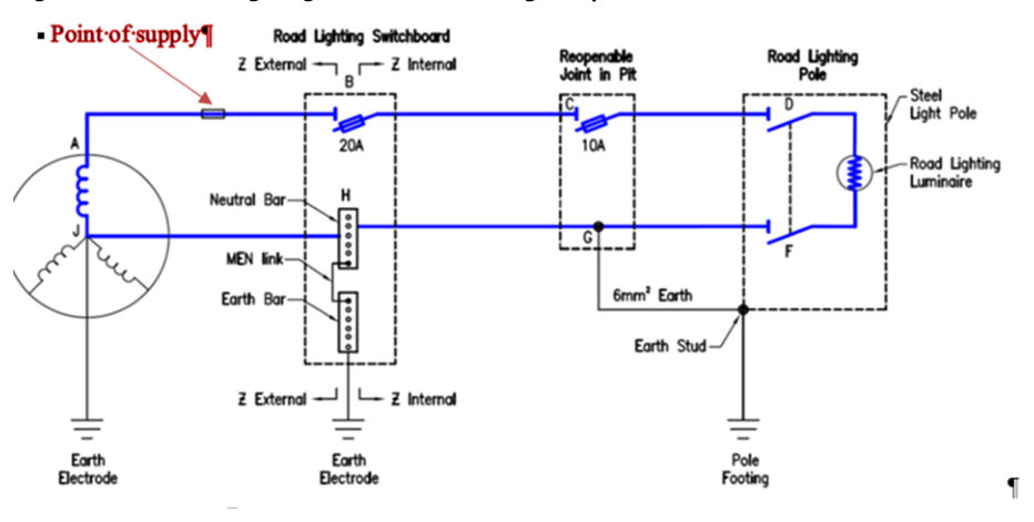
The voltage drop on startup must not exceed the minimum voltage required for the last luminaire on the circuit to strike. Ignitors used in control gear are generally designed for 220–240 V supply and they are required to operate (trigger) at a voltage of 90% of the nominal. This means that the minimum voltage for ignitor function is 90% (that is, -10%) of 220 V which is 198 V.
| Mains design voltage | 230.0 | |
| Allowable mains variation | -6% | -13.8 |
| Minimum allowable voltage at point of supply | 216.2 | |
| Allowable voltage drop in installation | -5% | -11.5 |
| Voltage at last luminaire | 204.7 | |
| Minimum allowable voltage on startup | 198.0 | |
| Allowable maximum voltage drop on startup | -2.9% | -6.7 |
From this, the maximum voltage drop in the installation at startup that will allow the last luminaire on the circuit to start is 7.9% or 7% to be conservative.
7.12.3The √3 factor in three-phase#
In a star connected circuit with the neutral at the star point, it can be seen in the following figure that, in any phase, the phase and line currents are equal; however, the line voltage (voltage between any two line conductors) is greater than the voltage across an individual phase. The relationship between the phase and line voltages can be determined by the use of vectors. In a balanced system, the phase difference between any two phases is 120⁰.
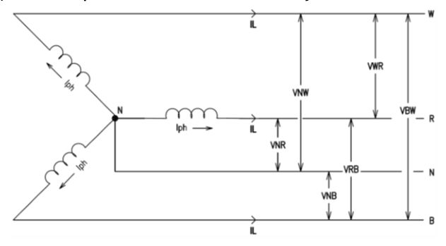
The line voltage (VRB) is equal to the vectorial resultant of the two-phase voltages VNR and VNB. If the external circuit from R to B is considered, then VNR is in the same direction as VRW but VNW is in the opposite direction; therefore, the line voltage VRB must be the vectorial difference between VNR and VNB. To obtain VRB, VNB is reversed, called VBN and the resultant VRB is obtained by completing the parallelogram of vectors.
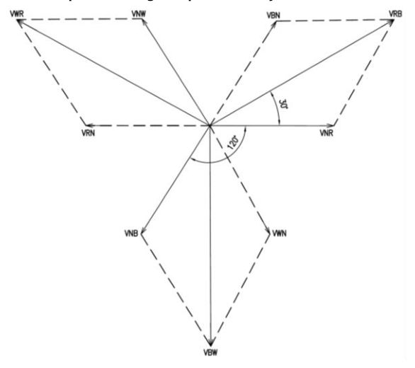
In the parallelogram of voltages following, the sides are equal to Vph and the diagonal is equal to VL. The angle between Vph and VL is 30⁰. The line ab is drawn to bisect VL and form the triangle abc.
The triangle is a 30⁰, 60⁰, 90⁰ triangle and so the sides are in the ratio 1, 2, √3.
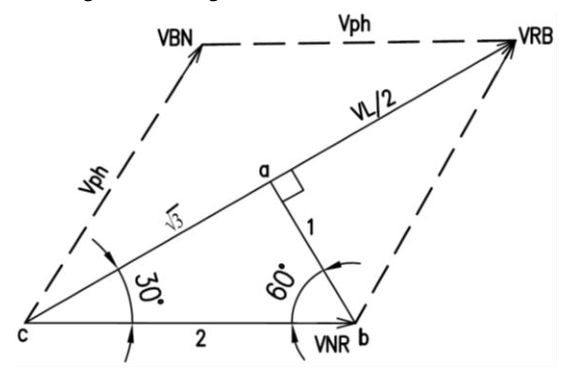
In the triangle abc:
cos 30o = b/c = (Vph x 1/2)/VL
but cos 30o = √3/2
therefore (Vph x 1/2)/VL = √3/2
or VL/Vph = √3
and IL/Iph = √3
where VL = line voltage Vph = phase voltage IL = line current Iph = phase current
7.12.4Relationship between AS/NZS 3008.1.1 Tables 30 and 35, and 42#
Using the information contained previously, the relationship between AS/NZS 3008.1.1 Tables 30 and 35, and Table 42 can be established; for example, take 1000 m of 35 mm² XLPE / PVC multicore cable with circular copper conductors operating at 75°C carrying a current of 10 A.
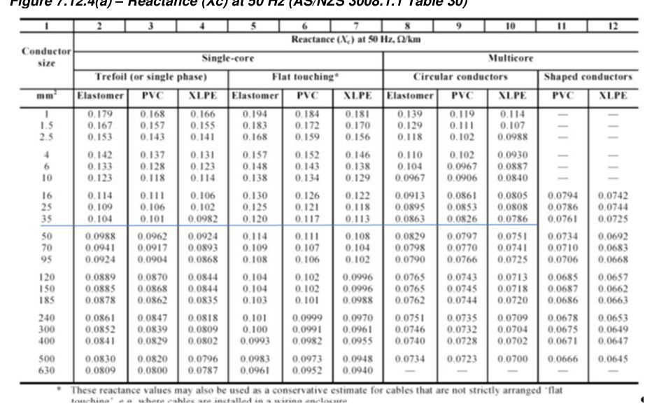
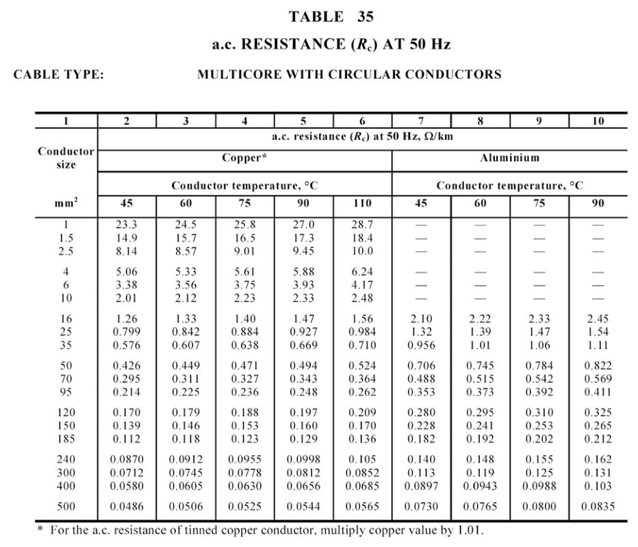
Therefore the impedance is
The three-phase voltage drop is (include the √3 factor for three-phase)
The single-phase voltage drop is (include the two factor for single-phase)
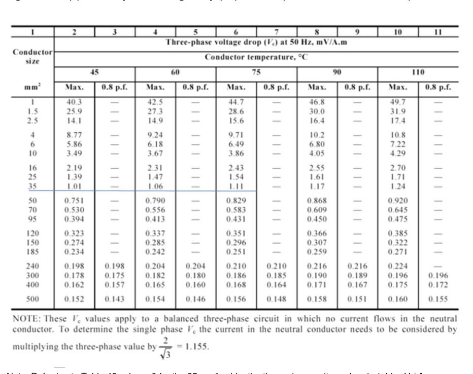
The three-phase voltage drop is
The single-phase voltage drop is (include the factor 1.155)
When calculating voltage drops using AS/NZS 3008.1.1, the cable reactance and resistance (Tables 30–39) or the three-phase voltage drop (Tables 40–51) may be used. Both methods should produce the same result.
7.12.5Maximum cable length for voltage drop#
For any core of a cable the single-phase voltage drop will be given by the following equation:
where
- V
- voltage drop in the core in volts
- I
- current in the core in amperes
- L
- L is the length of the core in metres
- Z
- Impedance of the core in ohms / km from AS/NZS 3008.1.1 Tables 30 and 35.
For a circuit of active and neutral cores the circuit voltage drop will be the sum of the voltage drops in the active and neutral cores as follows:
For any particular circuit, the length of the active and neutral is assumed the same, but the current in the cores and the core cross-sectional area may be different. The maximum allowable voltage drop in the circuit (Vd) will be the sum of the voltage drops in the active and neutral (note that this may not be the full 5% or 11.5 V). Then:
where
- Vd
- maximum allowable voltage drop in cable in volts
- Lmax
- the maximum length of the cable in metres (cable route)
- Ip
- current in the active in amperes
- Zp
- impedance of the active in ohms / km from AS/NZS 3008.1.1 Tables 30 and 35
- In
- current in the neutral in amperes
- Zn
- impedance of the neutral in ohms / km from AS/NZS 3008.1.1 Tables 30 and 35.
Where the active and neutral currents are the same for a single-phase system and the cores are the same cross-sectional area:
Similarly, for three-phase:
During the design process, the voltage drop will be proportioned between the consumers’ mains, submains and the sub-circuits. The maximum voltage drop in these equations is the proportion appropriate to the selected cable.
Where the cable sizes are small, the reactance is very small compared with the resistance and can be neglected. In this case, Z = R.